|
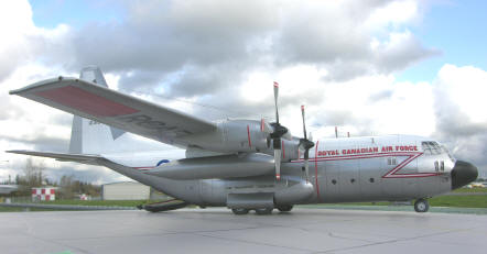
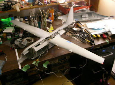
For many years, I have had Italeri’s monster C-130E kit sitting in my stash
just waiting to be built. With a kit of this size it was crying out for
something a bit more than just “a build”…it needed some life, and after
reading an old FineScale Modeler magazine for the umpteenth time, I decided
to try my hand at adding fibre optics and LEDs. Initially all I could fine
in the LED department were 5 mm lights at Radio Shack and with the space in
the wing tips being very limited, they would not do. I did find some 3 mm
LEDs at a electronic supply store in Langley, BC but they were not very
bright so the lighting system was put on the back burner for a while so that
I could start with re-scribing all of the panel lines on this hugh piece of
plastic. |
 |
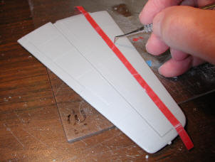 |
I started
with the stabilizer, a roll of Dymo labelling tape and a dental pick which I
sharpened to remove a fine “curl” of plastic. Three passes were all that it
took to get a very fine panel line. |
|
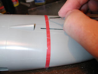
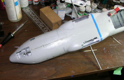
I next taped the fuselage halves together then started scribing the miles of
panel lines. There were a few “OOPS” along the way but eventually it turned
out quite well…for the first truly big re-scribing job. There were some
interesting shapes that needed special attention; the biggest being the wing
root fairing on the fuselage. |
 |
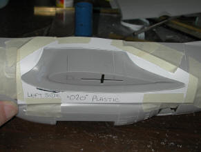 |
The wing
root template was copied from the raised panel lines using thin paper and a
soft pencil, then transferred to .020 plastic sheet. The centre was
removed, sanded smooth then taped to the fuselage and the fairing scribed
into the plastic. Both sides were done by flipping the template. |
|
The wings and vertical tail were re-scribed and when every panel line on the
model was given the treatment, all components were sanded with 400 wet sand
paper then washed with liquid dish soap and an old tooth brush. The model
sat under my model table for over a year after I had put in about 100 hours
with the panel line nonsense and occasionally I would try connecting LEDs,
variable resistors and other components. Initially I had intended that the
wings would be removable and to this end, I used square brass tubing for
centre section carry-through and wing spars. |
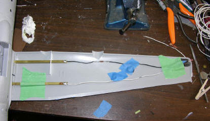 |
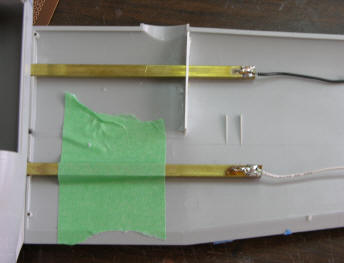
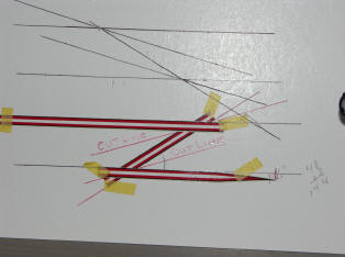
A template
of the wing end root was made using .020” plastic card and the tubing
cut-outs were removed. A false wing rib was added outboard of the inner
engine nacelles. The LEDs were wired to the brass spars and these were then
epoxied into the wings. Trying to figure all of this out was pretty time
consuming and over time, newer LEDs were produced which gave out much more
light over a wider area. These were substituted for the original LEDs.
I then added Milliput epoxy in the wings at the root for strength..not
shown here. Once the spars had set up they were set aside while the
electronics were taken care of. |
|
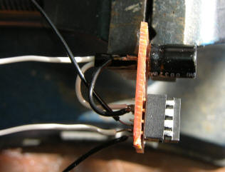
The Hercules has two anti-collision lights, one on the top of the vertical
tail and one on the bottom of the fuselage aft of the nose gear rear door.
To make these realistic I used two Superbright Red LEDs wired to a socket
which would take an LM3909 chip. Using the wiring diagram in FSM, I wired
up the socket, plugged in the chip and applied power to the LED circuit…and
we had flashers! The LED was epoxied into the top of the fin and the wires
which would eventually provide power were brought out through the end of the
dorsal fin…where they would eventually be routed through the top of the
fuselage. |
 |
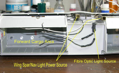 |
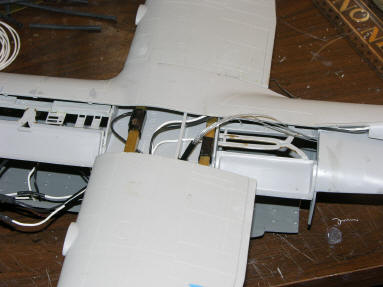
Now it was
time to tackle the fuselage. The wiring was inserted in the wing centre
section and the two brass carry-throughs were used for the Positive and
Negative contacts for the wings. I added a Super Bright White Led in the
left side of the fuselage over the wheel well and routed the wires through
the bulkhead into the forward cargo area. |
|
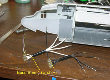
I needed a secure system for the power supply so I cut
two strips of brass, added the white negative wires to one and the black
positive wires to the other. I then had the cockpit lighting to worry about
and not having any photos of a Hercules instrument panel with lights, I
decided to use only one Super Bright White LED to the top of the cockpit
bulkhead to light the entire cockpit.
The nav lights in the tail are made from fibre optics
and these plus the cargo bay overhead lights, also fibre optics, were
plugged into a piece of plastic tubing which had a SB White LED in the other
end. The tubing was then painted black for maximum light retention.
|
 |
 |
 |
|
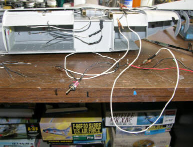
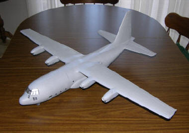
The fuselage was now taped together, the wings and vertical tail added and
the power was hooked up. Testing for lighting serviceability must be
carried out frequently before the whole thing is assembled. |
 |
 |
|
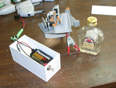
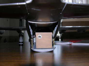
The fibre optic bundle was tested and then tucked into the fuselage/wing
centre section and epoxied in place. I used heat-shrink tubing to keep the
fibre bundle together. The power supply, a 9 volt battery, was housed in a
plastic “crate” which I made out of Sheet and strip Evergreen plastic. The
On/Off switch was wired into the end of the box which was painted with
Humbrol “WOOD” acrylic using a stiff bristled brush. |
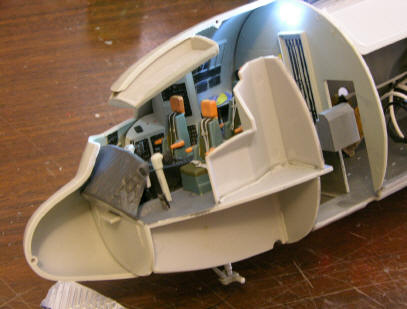 |
I found
numerous very different cockpit photos of the Hercules and there were as
many versions as there were aircraft. With the help of ARC members and my
supply of photos, I detailed the instrument panels, the overhead and side
panels and added photo-etched seat belts, and placed a coloured map on the
Navigators desk. To cover the void behind the instrument panel, I cut a
piece of aluminum foil, embossed it with a diamond pattern stitching using a
toothpick, painted it flat black and super glued it in place. Because of a
lack of cockpit lighting photos, I installed a Super Bright White LED near
the top of the cockpit bulkhead and wired it into the buss bars. This gave
off sufficient light to illuminate the cockpit without too much glare. |
 |
 |
|
It was now time to close things up. The vertical tail was glued to the
right side of the fuselage and the wiring fished through to the buss bars
and flasher unit. The square brass carry thoughs were secured with Milliput,
the kit supplied spar glued in place and the fuselage taped together. The
wings were slid into place and quickly taped into position and the whole
thing set aside for 24 hours to give the Milliput time to cure. |
|
The wings were removed and the fuselage reopened for
final wiring…and testing. With everything working properly, the fuselage
was glued together, the fin glued to the left side of the fuselage and the
wings glued into position. The stabilizors were glued into position and
everything squared up as the glue cured. I installed the prefinished
landing gear into the wells which had been detailed and painted.
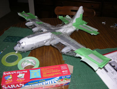
Windows in the fuselage were masked, Kleenex stuffed
into all openings and the monster was ready to paint. |
 |
 |
|
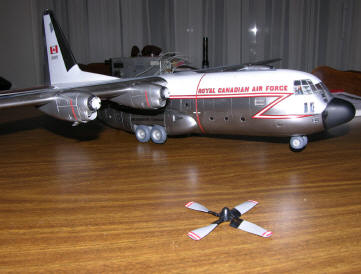
I touched up the panel lines over the top of the fuselage and wing roots
then sprayed the walkway areas flat grey using Polly Scale. I then masked
over the walkways and sprayed the top with Model Master Gloss White…over a
coat of Polly Scale White. I then masked over the white and masked the wing
tips and horizontal tail for the Model Master Guards Red. |
All of the
prepainted areas were masked and then I sprayed the bare areas with Alclad
II Gloss Black Primer. Two days later, I sprayed the Alclad II Polished
Aluminum and when the tapes came off, so did the paint…lots of bare plastic
showing. After sanding and re-spraying the painting was finished…or so I
thought! |
 |
 |
|
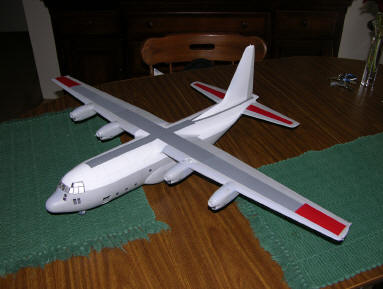
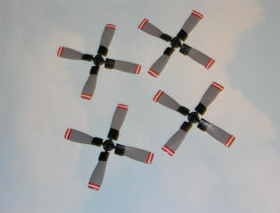
While waiting for the paint to dry, I painted the props using Polly Scale
and when dry, I used strips of decal to complete the warning stripes on the
tips. This gives a much better finish than trying to mask and paint. |
The
fuselage flash line was from an old set of Canforce Decals and had to be cut
to size. I made a template on gloss white card, taped the decal in place
and cut them to length. The pieces fit perfectly when applied to the model. |
 |
 |
|
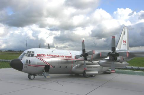
Some of the decals; the tail and underwing numbers along with the “Last Two”
on the nose, and the black drop-shadow outline on the “ROYAL CANADIAN AIR
FORCE” red lettering were made using Coreldraw 10 and printed on a HP
laserjet 4P. |
The cargo
bay ramp and doors were glued into position and brass tubing used for the
ramp braces. The “cargo” was installed and after adding the gear doors and
antennae the monster was finished…except for the paint under the windshield
that came off while trying to get rid of the Bare Metal Foil goo. Touch-ups
were made but not to my satisfaction…maybe another time in another life….! |
 |